
Understanding Subpart W: LDAR Strategies for Method 2 and Method 3 Compliance in Pneumatic Devices
February 26, 2025
By: Ed Capozzi and Elizabeth McGurk
The way emissions are measured in the oil and gas industry is changing. For years, default emission factors have been the standard for estimating greenhouse gas (GHG) emissions, but what if those estimates have been overstating—or even understating—what’s really happening in the field?
In 2024, the U.S. EPA updated several subparts of the Greenhouse Gas Mandatory Reporting Rule (GHG MRR), including Subpart W, which governs annual GHG reporting for the oil and gas industry (see our detailed analysis of the latest Subpart W updates here). The revisions aim to improve the accuracy of emissions inventories by requiring the inclusion of previously unreported sources and encouraging the use of empirical, site-specific data to develop measurement-informed inventories.
At Montrose, we’ve seen firsthand how measurement-based LDAR methodologies can significantly alter emissions profiles—often revealing lower emissions than traditional estimates. This is particularly true for the pneumatic device venting source category, which now includes three measurement-based methods for calculating emissions in addition to an emission factor and population-based method:
- Method 1: Continuous flow meter installation
- Method 2: Volumetric emissions measurement
- Method 3: Video-based malfunction screen
- Method 4: Default emission factor + population-based approach
This blog will focus on how to perform the fieldwork required for Methods 2 and 3 above, which are the two measurement-based LDAR methods Montrose clients have implemented for pneumatic device venting emissions quantification. Accurate measurement and record keeping not only ensures compliance but also highlights opportunities to mitigate emissions and improve efficiency. Regardless of which method is chosen, with the right tools—like Target Online—teams can streamline LDAR data management, making tracking, analysis, and reporting more efficient and reliable.
To better understand how each method works and when to apply them, let’s take a closer look at the specifics of Method 2 and Method 3 for pneumatic device venting emissions measurement.
Pneumatic Device Method 2: Volumetric Flow Rate Measurement
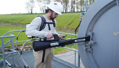
Using Method 2, a technician measures emissions from the pneumatic device vent by directly measuring the volumetric flow rate using specialized devices, such as a high volume sampler (e.g. the SEMTECH HI-FLOW 2). The rule also allows for the use of calibrated bags, but high-volume samplers offer a higher-degree of accuracy and control in practice. Under Method 2, measurements are obtained for a minimum of 15-minutes per device and then extrapolated to estimate emissions throughout the year.
Benefits
- This method offers high accuracy for measuring emissions.
- Site-specific measurement data provides the most complete understanding of actual emissions from an operation, which means a more accurate emissions inventory, not only for reporting, but also for evaluating site modifications to decrease GHG emissions most effectively.
- Using this method, Montrose clients have realized significant decreases in reported emissions compared to those calculated using Method 4 default emission factors.
Elements for Consideration
- This method is applicable to continuous and intermittent-bleed devices in all industry segments required to report emissions from pneumatic device venting.
- For Onshore Production and Gathering and Boosting using Method 2, it must be used for all pneumatic device vents at a single site not using a continuous flow meter. Different methods can be used at different sites in the reporting facility (basin). You must perform measurements each reporting year for which you wish to use measurement data and cannot develop emissions factors for use on devices that were not measured during the reporting year.
- For Onshore Natural Gas Processing, Onshore Natural Gas Transmission Compression, Underground Natural Gas Storage, or Natural Gas Distribution facilities using Method 2, all devices not using a continuous flow meter must be measured. Measurements can be performed over a time period of up to five years, depending on the total number of pneumatic devices. As measurements are completed, the reporting facility will use the measurements to develop an emission factor to apply to the portion of the population that has not yet been measured.
- High volume samplers (i.e. the SEMTECH Hi-Flow 2) are specialized equipment, which may necessitate additional resources and training, even if a site has an in-house OGI (optical gas imaging) team.
- Because this method requires a 15-minute measurement per device, it is time consuming.
Field Considerations
- Equipment Needed: High-volume samplers or calibrated bags
- High-Volume Sampler Calibration: Daily performance verification to ensure the equipment is functioning correctly by comparing measurements against a known, calibrated gas source
- Crew: Two personnel – one to identify pneumatic device vents, ensure full emissions capture using an OGI camera, and to assist with recordkeeping; the other to operate the high-volume sampler
Pneumatic Device Method 3: Intermittent Bleed Device Malfunction Screen Using OGI
In Method 3, a technician uses an OGI camera to evaluate whether an intermittent-bleed device is malfunctioning or operating as designed. The operator uses the OGI camera to visualize whether the device is emitting when it is not actuating. If it is, the device is determined to be malfunctioning. When preparing annual emission calculations, the reporter uses different EPA-provided emission factors per count of malfunctioning and non-malfunctioning device. Unlike Method 2, no volumetric measurements are taken or used in the calculation.
Benefits
- This method is effective for quickly evaluating whether pneumatic devices at a site are malfunctioning. It is much quicker than Method 2, above, for obtaining site-specific data to use in reporting.
- OGI is also beneficial for evaluating emission points that may be difficult to reach with high-volume sampler as it provides rapid screening with minimal disruption to operations. The visual evidence supports compliance documentation, delivering clear and immediate records of emissions observations.
- Even though this method does not provide site-specific emission rate data, it provides insight into malfunction rates of pneumatic devices that can be analyzed to inform maintenance and/or replacement strategies.
- Using this method, Montrose clients have realized significant decreases in reported emissions compared to those calculated using Method 4 default emission factors.
Elements for Consideration
- This method is applicable only to intermittent-bleed devices and can only be used by the Onshore Production and Gathering and Boosting industry segments.
- For Onshore Production and Gathering and Boosting facilities using Method 2, it must be used for all pneumatic device vents at a single site not using a continuous flow meter. Different methods can be used at different sites in the reporting facility (basin). You must perform screening each reporting year for which you wish to use the data.
- Accurate interpretation of the OGI video footage to determine whether the device is malfunctioning relies heavily on both industry expertise and understanding the regulatory definition of what constitutes a malfunction.
- The rule includes specific requirements of allowed bleed time before a device must be categorized as malfunctioning.
- There are recordkeeping requirements for specific types of devices that are designed and expected to exceed the bleed time defined for a typical malfunction.
- Method 3 requires a dwell time of at least two minutes per device, or until the device actuates, whichever comes first.
Field Considerations
- Equipment: OGI cameras that meet Subpart W requirements for OGI
- OGI Camera Daily Verification Check: Daily performance check against a known volume regulator to ensure accuracy and reliability in emissions detection
- Video: although not required, recommend collecting video for the duration of the two-minute observation
- Crew: One or two personnel, depending on site size and number of pneumatic devices to be evaluated
Key Takeaways
The recent revisions to the Subpart W reporting rule allow flexibility in choosing calculation methodologies that are the right fit for their reporting facilities. The methods are not one-size-fit-all, and the correct methodology for a site will be impacted by several different factors, including but not limited to operations at the location and the potential impact of the specific emission source on the total reported footprint.
This article summarized pneumatic device calculation methods 2 and 3. At a high-level, Method 2 provides actual volumetric emission rate data per device for use in annual emission calculations. Method 2 can be used for all types of pneumatic devices in all industry segments. With a measurement time of at least 15 minutes per device, it is also time consuming. Method 3 is an OGI-based malfunction screen that can only be used on intermittent-bleed devices and by the Upstream Production and Gathering and Boosting industry segments. You use a combination of actual malfunction rates and EPA emission factors to calculate annual emissions. Because it is OGI-based and only requires two measurements per device, it can likely be integrated into existing OGI surveys with some additional training.
By understanding the strengths and applications of each method, your organization can meet regulatory requirements, gain information about your site-specific operations to be used in maintenance and emissions reduction planning, and likely lower your reported GHG emissions footprint. A tailored approach to emissions measurement will help your facility stay ahead of regulatory challenges and contribute to a more sustainable future.
Want to optimize your GHG reporting? Contact us today for a consultation on the best measurement options for your operations!
Continue Reading

 Ed Capozzi
Business Development Manager
Ed is a Business Development Manager for Montrose Environmental’s LDAR team, specializing in emissions compliance solutions, Optical Gas Imaging (OGI), and regulatory-driven leak detection programs. With a background in Saas, IoT, automation, and industrial services, Ed brings a strategic, data-driven approach to helping clients navigate complex compliance challenges. With over a decade of experience, Ed has a proven track record of building lasting client relationships. His expertise spans LDAR compliance, emissions testing, and environmental regulations, making him a valuable resource for industries seeking to optimize their compliance programs.
 Elizabeth McGurk
Methane Market Sector Leader
Elizabeth is a highly-experienced air quality program manager with expertise in the fields of greenhouse gas (GHG) quantification and mitigation, oil and gas sustainability framework implementation, regulatory analysis, and auditing. Her passion is in leveraging measurement-informed data to inform effective mitigation efforts, and she is proud to have supported OGMP 2.0 projects worldwide. Elizabeth has a strong background in delivering technical trainings and excels in distilling and presenting complex information, impacts, and solutions to various stakeholders. She leads diverse teams and has conducted complex environmental projects, both regulatorily and voluntarily driven, for clients in carbon-intensive industries. She specializes in assisting clients with Scope 1, Scope 2, and Scope 3 GHG emissions quantification and reporting as well as in developing practical, real-world carbon reduction strategies.